
Jack Schmitt's Apollo 17 Suit
Photographed at the National Air and Space Museum's Garber Facility in July 2004 by Ulrich Lotzmann under the guidance of Amanda Young and Bill Ayrey.
Last revised 18 September 2006.
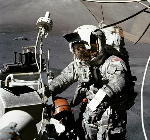
A detail from AS17-134-20472 shows Jack Schmitt at the Rover during the EVA-3 Close-out.
Lotzmann write "According to Amanda Young, this suit is in the very best condition of all flown lunar surface suits. It shows only minor damages. She emphasized that as long as she has something to do with preserving the lunar suits, this specific suit will never be displayed again.
- EVA Gloves ( 39k )
- View of both gloves with palms up.
- LEVA (Lunar Extravehicular Visor Assembly)
( 237k )
- View of the lefthand side showing the hard, top surface containing the upper sunshade and, inside, the hinge assembly on the righthand side for the visors and side shades. Diagrams and a discussion can be found in an extract from the EMU Handbook.
- LEVA (Lunar Extravehicular Visor Assembly)
( 210k )
- Close-up of the LEVA hinge assembly.
- LEVA (Lunar Extravehicular Visor Assembly)
( 237k )
- View of the front-left showing the tabs used to pull down the visors and sunshades. The rightmost tab in the image and its counterpart on the other side are used to pull out the side sunshades. The next tab and its counterpart on the other side are used to pull down the inner, protective visor which provides both micrometeoroid and ultraviolet protection. And the two inner tabs are used to pull down the gold-electroplated sun visor which provides relief from bright sunlight and reduces heating of the inside of the helmet. At the top, a broad tab is used to pull down the upper sunshade.
- LEVA (Lunar Extravehicular Visor Assembly)
( 231k )
- View of the front-left. Note the multi-layer covering at the bottom, front which, after the LEVA is latched to the bottom of the pressure helmet, protects the neckring from dust and solar heating. Diagrams and a discussion can be found in an extract from the EMU Handbook.
- LEVA (Lunar Extravehicular Visor Assembly)
( 263k )
- View from the left-front with the protective visor down. Amanda Young of the National Air and Space Museum is holding the LEVA.
- LEVA (Lunar Extravehicular Visor Assembly)
( 236k )
- View from the left with the sun visor down.
- LEVA (Lunar Extravehicular Visor Assembly)
( 202k )
- View from the left-front with the sun visor down. At 165:01:54, some one in Houston notices that Jack has his sun visor up and CapCom Bob Parker urges him to pull it down. Jack replies, "Well, I think I might...I can't see with it down; it's scratched! Bob, I'll use it." We may be seeing some of the scratches in this view.
- LEVA (Lunar Extravehicular Visor Assembly)
( 210k )
- View from the bottom. The front of the LEVA is at the top of the image. Note the velcro closures on the neckring cover.
- LEVA (Lunar Extravehicular Visor Assembly)
( 221k )
- View from the bottom. The front of the LEVA is at the top of the image. Note the velcro closures on the neckring cover.
- PGA (Pressure Garment Assembly)
( 276k )
- View of the front of the suit from the feet toward the neck.
- PGA (Pressure Garment Assembly) Neckring
( 280k )
- View from the top. The communications cable and connector is on the inside-right. Compare with a detail from Figure 2-14 in the EMU Handbook.
- PGA (Pressure Garment Assembly) Neckring
( 313k )
- View from the right front. Note that the lock subassembly, marked "Class III Not for Flight". Ulli writes, "These red 'Class III Not for Flight' labels were also used for downgrading flown hardware. If you see artifacts with such a label in a museum, they can be flown. Sometimes you can also see red slash marks through the identifaction label and a handwritten 'Class III'. That, too, can mean the hardware is downgraded from its flown status."
- PGA (Pressure Garment Assembly) Left Shoulder
( 290k )
- View from above the shoulder toward the right hip. Note the pressure gauge just above the left wristring. The adjacent fitting on the left hip is a lunar module tether attachment as indicated in Figure 2-13 from the EMU Handbook. An identical fitting is on the right hip and these were used with floor-mounted tethers help keep the astronauts in place during both the descent and ascent. The RCU attachment point is just below the 'Schmitt' name tag and has a National Air and Space identification tag attached. The other fittings are identified in a labeled version of a similar photo ( 314k ).
- PGA (Pressure Garment Assembly) Left Shoulder
( 289k )
- View from the left shoulder across to the right arm. Note the shoulder pocket.
- PGA (Pressure Garment Assembly) Inner Left Arm
( 254k )
- View across the chest to the inner left arm. The comm port is at the upper left and the other two ports are for inflow of oxygen from the PLSS (nearest to the camera) and the OPS (farthest from the camera). See Figure 2-4 and related material from the EMU Handbook. See, also, Karl Dodenhoff's connector layout diagram. The cloth strap holding the suit arm close to the torso is not part of the suit.
- PGA (Pressure Garment Assembly) Outer Right Arm
( 256k )
- View from the right of the sleeve, wristring, and rightside LM tether attachment.
- PGA (Pressure Garment Assembly) Left Wristring
( 229k )
- This view is dominated by the locking ring. If 12 o'clock is up, there are lock tabs at 10:30 and 1:30. Alignment marks can be seen at 2 o'clock. In order to attach the glove, the lock button at 12 o'clock is depressed, the two lock tabs are pulled down - that is, along the arm axis away from the shoulder - and the locking ring is rotated to the right (clockwise) to the 'Open' position. As per Figure 2-15 in the EMU Handbook, the glove is inserted and seated and, with the free hand, the lock button is depressed, the lock tabs are pulled down, and the lock ring is rotated left (counterclockwise) until the lock button seats. At some point in the early 1990s, Joe Kosmo at NASA Johnson allowed me to examine one of John Young's Apollo 10 suits, then undergoing restoration. Even with bare hands, I found the wristrings difficult to operate. Dean Eppler, who works at JSC on EVA planning and suit devlepment and often wears either Shuttle or advanced-design suits in his work, writes in March 2005, "we still use the same system, although I've had far more trouble getting gloves off than on. I usually let the suit techs do it, in both instances; but about one suit run in every ten, I do it myself to convince myself if all the techs dropped dead or ran away, I could get myself out of the suit. People have asked me if there's a risk of losing a glove in space. I always tell them there's a far greater risk of getting a glove stuck on than accidently losing one."
- PGA (Pressure Garment Assembly) Pressure Gauge
( 331k )
- The dial is marked from 2.5 to 6.0 psi (pounds per square inch). Note the scratches on the cover over the 5.0 position. During the EVAs, normal suit pressure was 3.8 psi. During the initial stages of cabin depressurization, as the cabin pressure decreased the relative pressure in the suit increased for a time from about 3.8 psi to about 5.3 psi because the suit pressure relief valve could not bleed oxygen fast enough to keep pace with the decreasing cabin pressure. Eventually the cabin pressure fell low enough that the relief valve could ahve a noticeable effect and suit pressure fell toward 3.8 psi.
At various times during the EVA, when the Flight Surgeon recommended to the Flight Director that Gene or Jack take it easy, CapCom Bob Parker would ask them to make an 'EMU check', which included readings of suit pressure and remaining oxygen. the scratches undoubtedly resulted when Jack used the fingers on his dust-impregnated right glove to clean dust off the gauge.
- PGA (Pressure Garment Assembly) Chest Fittings
( 315k )
- Close-up of the chest from over the left shoulder. The connectors are identified in a labeled version ( 314k ). Blue connectors are for flow into the suit and blue connectors for outflow. The diverter valve, which is between the RCU attachment and the red tag, " directs the inlet gas flow to the helmet duct (valve in the Close position) or diverts a portion of that flow to the torso duct (Open position) as preferred by the crewman. The ventilating gas flows from the helmet down and over the body to the arm and leg extremities to removebody gas perspiration and heat. Outlet gas flows from the extremities through ducts to the exhaust connector. " See Figure 2-4 and related material from the EMU Handbook.
- PGA (Pressure Garment Assembly) Chest Fittings
( 274k )
- Close-up of the chest from outside the left hip. Note that each of the hose connectors has a locking ring and a pair of tabs which are lifted as the locking ring is rotated clockwise to lock ('L') the hose into the connector or counterclockwise to open/release ('O') the connector. A third tab is used to prevent the locking ring from turning and, hence, is called a "lock-lock" On the connector closest to the camera, the lock-lock is on the far side and is up, in the open position.
- PGA (Pressure Garment Assembly) Chest Fittings
( 274k )
- Close-up of the chest from outside the right hip. Figure 2-16 in the EMU Handbook shows exploded views of the gas connectors and the diverter valve.
- PGA (Pressure Garment Assembly) Attachment for the Lower PLSS Straps
( 351k )
- Close-up.
- PGA (Pressure Garment Assembly) ILC Label
( 335k )
- Close-up.
- PGA (Pressure Garment Assembly) Left Hip Area
( 267k )
- Showing the Lower PLSS Straps fitting at the waist, the righthand LM Tether attachment on the hip, and a partly open Utility Pocket that covers most of the left thigh. See Figure 2-1 ( 150k ) from the EMU Handbook.
- PGA (Pressure Garment Assembly) Pencil Pocket, Penlight Pocket, and Biomedical Injection Disk
( 350k )
- The pencil pocket covers the center of the ultility pocket, with the penlight pocket below it in this image. The biomedical injection Disk is between the bottom of the penlight and the utility-pocket fastener at the lower left. See Figure 2-1 ( 150k ) from the EMU Handbook.
- PGA (Pressure Garment Assembly) Left Thigh and Knee
( 267k )
- Showing the area beneath the utility pocket. Dean Eppler notes that, in training photo KSC72PC-440 taken in July 1972, shows no Velcro strips below the utility pocket and two short, vertical strips on the right knee.
- PGA (Pressure Garment Assembly) Cover for Pressure Relief Valve and UCTA Connector
( 369k )
- This close-up shows the top part of the right thigh. See Figure 2-1 ( 150k ) from the EMU Handbook.
- PGA (Pressure Garment Assembly) Right Thigh
( 350k )
- Showing a snap fastener at the bottom of the cover for the relief valve and UCTA connector. See Figure 2-1 ( 150k ) from the EMU Handbook.
- PGA (Pressure Garment Assembly) Right Knee
( 363k )
- Close-up.
- PGA (Pressure Garment Assembly) Lower Legs
( 264k )
- View from above the right hip.
- PGA (Pressure Garment Assembly) Right Boot
( 252k )
- Close-up.
- Right Lunar Boot
( 256k )
- View from the righthand side. The lunar boots slipped over the PGA boot and were held in place by straps.
- Right Lunar Boot
( 304k )
- View from the lefthand side. Note the pattern of cleats
- Right Lunar Boot Sole
( 193k )
- View from the lefthand side. The darker areas are the cleats.