
ECS Equipment - Water Management Section
Descent Water Valve The descent water (DES H20) valve (see Water Control Module, below) is a manually operated, poppet-type shutoff valve. The valve has open and closed positions. In the open position, the valve provides high-pressure water flow from the descent tank to the water dispenser.
Ascent Water Valve The ascent water valve, at the top of the water control module (see Water Control Module, below), is a manually operated, poppet-type shutoff valve. The valve has open and closed positions. In the open position, the valve provides high-pressure water flow from the ascent tank to the water dispenser.
The WQMD measures the quantity of water by sensing the pressure/temperature ratio of the tank pressurizing gas. This ratio decreases as the gas expands in expelling the water. An analog computer subtracts a voltage inversely proportional to the pressure/temperature ratio from a set constant voltage, which represents the total volume of the tank. The result, tank volume minus gas volume, is water volume.

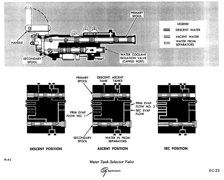
Water Tank Selector Valve The water tank selector valve is a manually operated, three-position, two-spool valve (see Water Control Module, above). The two spools (primary and secondary), linked to the valve handle, rearrange the internal ports to establish proper flow paths. The valve has descent, ascent, and secondary positions. In the descent position, the primary spool establishes a flow path between the descent water tank and the primary water manifold. In the ascent position, the primary spool establishes a flow path between the ascent tanks and the primary water manifold. When the valve is in the secondary position, flow is diverted from the ARS separator to the secondary manifold and water is routed from the ascent water tanks to the secondary manifold.
Primary Evaporator Flow Valve No. 1 The primary evaporator flow No. 1 valve is a manually operated, poppet-type shutoff valve (see Water Control Module, above). It has open and closed positions. In the open position, the valve allows flow from the ascent or descent water tanks, through the primary regulators, to the primary sublimator.
Primary Evaporator Flow Valve No. 2 The primary evaporator flow No. 2 valve is a manually operated, poppet-type shutoff valve (see Water Control Module, above). It has open and closed positions. In the open position, the valve acts as a backup to the primary evaporator flow valve to provide ascent tank water from the secondary water manifold to the primary sublimator.
Secondary Evaporator Flow Valve The secondary evaporator flow valve is a manually operated, poppet-type shutoff valve. It has open and close positions. The valve controls water flow from the secondary water manifold to the secondary sublimator and to the suit circuit sublimator.
Water Pressure Regulator Module The water pressure regulator module consists of a pressure regulator and a manifold. The module is located in the secondary water circuit, downstream and in series with the secondary water pressure regulator in the water control module.