
Apollo Drawings by James T. Burns
Drawings copyright by James T. Burns. All rights reserved.
Captions by Eric M. Jones
Last revised 16 June 2016.
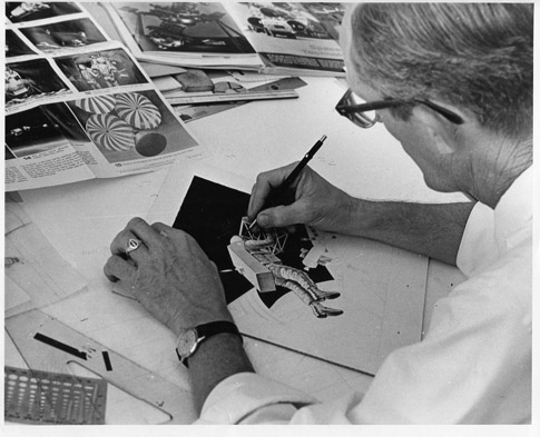
| Jim Burns worked as a illustrator at RCA Government Systems Division for twenty-nine years, retiring at the end of 1989. See, also, his biographical sketch at the bottom of this page. Here, Jim is working on a drawing for an RCA concept of a Voice-Controlled Propulsion Backpack which, like the Manned Maneuvering Unit flown on three Shuttle missions in 1984, may be derived from the US Air Force Astronaut Maneuvering Unit. |
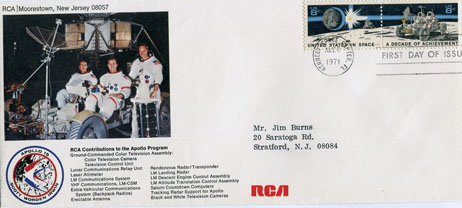
| Apollo 15 First Day Cover from Jim's collection of Apollo memorabilia. At the lower right is a list of RCA Contributions to Apollo. |
Voice, TV, and Data Links for Apollo 11 to 14
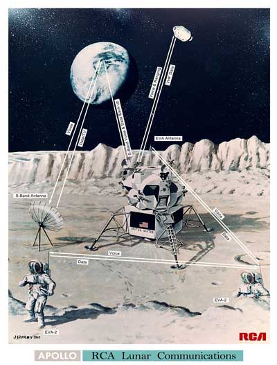
Apollo 15 Extravehicular Communications Systems
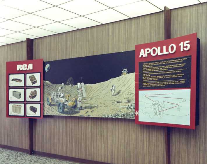
Display at RCA Jim created, showcasing RCA contributions to Apollo 15
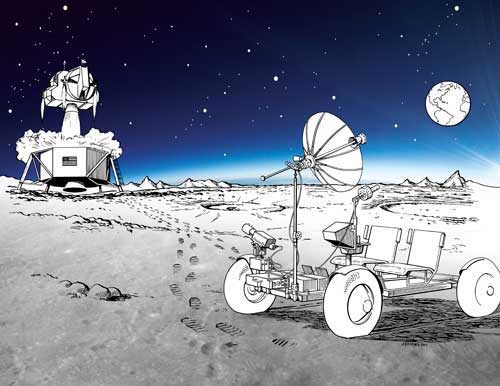
| The Lunar Roving Vehicle (LRV) allowed the crew to go farther from the LM and to carry more tools and sample than would have been possible otherwise; and to arrive rested and ready for up to an hour of sampling at each geology stop. The communications gear the Rover carried - the remotely controlled color TV camera, the Lunar Communications Relay Unit, and the high-gain antenna - made it possible for flight controllers and mission scientists to monitor activities and offer pertinent advice and direction. The comm gear also provide front row seats for the global television audience and covered the return of the Ascent Stage to lunar orbit. |
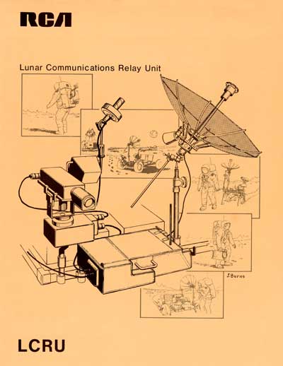
Lunar Communications Relay Unit (LCRU)
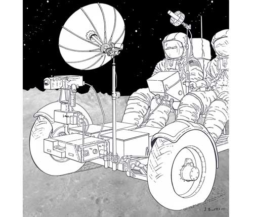
| The LCRU rode on the front of the LRV. The TV was mounted on the Television Control Unit just on the other side of the LCRU. The high-gain antenna is not shown, except for the lower part of its mast on the near side of the LCRU. The low-gain antenna (voice only) was mounted next to the LRV control panel, just forward of the LRV control handle operated by the Commander in the near seat. Normally, only voice and PLSS data were transmitted when the Rover was in motion. Only for a brief period during the Apollo 15 EVA-3 traverse did the crew attempt to send TV to Earth when in motion. Very little got through because of the need for accurate high-gain pointing. Normally, the TV was stowed pointing down and aft and the LCRU was set to send only voice and PLSS data. For LCRU details, see RCA's March 1971 Crew Training Manual (4 Mb). |
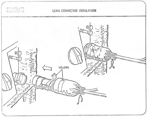
LCRU Thermal Blanket
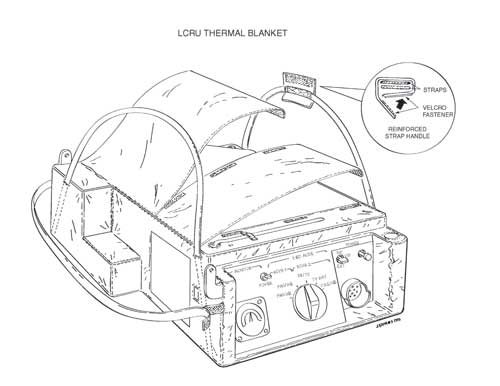
| When the Rover was in
motion, the covers were kept closed to keep dust off
the cooling mirrors on the top of the LCRU. When
the crew reached a site where the TV was to be used,
they opened the covers and cleaned any accumulated
dust off the mirrors to radiate away any excess heat
to space. In this view, the front of the LRV
would be to the left. |
Stitching the LCRU Thermal Blanket
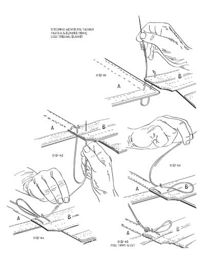
| The cable and connector
shown here connect the TCU (also known as the Ground
Controlled Television Assembly or GCTA) to the LCRU on
the righthand side of the unit. Cables from both
the high-gain and low-gain antennas connect on the
lefthand side of the LCRU, the side closest to the
TCU. See the LRV/LCRU Configuration illustration
below.
|
| Cover for LCRU Design Review Document submitted by RCA to NASA. |
Stowage Container for the High-Gain and Low-Gain Antennas
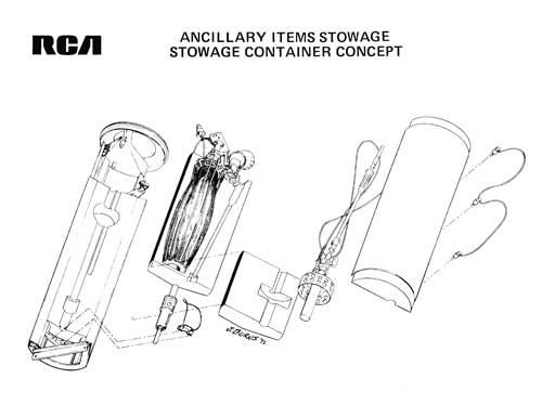
| Concept drawing:
Both LRV Antennas were stowed in this container which,
in turn, was stowed in the MESA. An Apollo
15 video clip shows Dave Scott working at the
MESA. He has removed the antenna canister from
the MESA and, as the clip starts, he is opening the
canister so he can removed the low-gain antenna and
take it to the Rover for installation. |
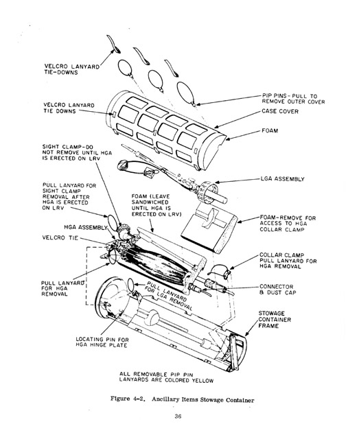
| Fully-annotated version of the Antenna Stowage Container drawing from the Crew Training Manual for the LCRU. |
High-Gain Antenna

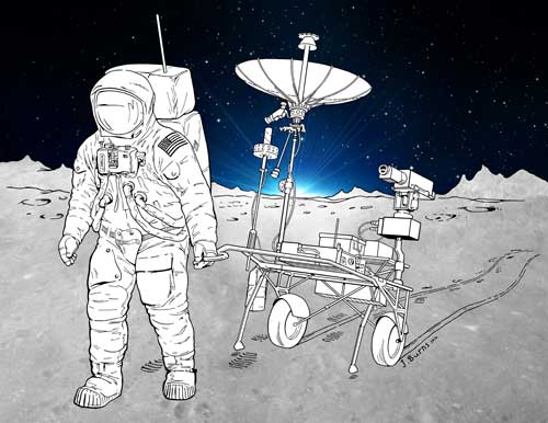
| The high-gain antenna produced a beam tight-enough that an adequate TV signal could be received by 85-m dishes on Earth. Pointing the antenna with sufficient accuracy was tricky because, when pointed correctly, Earth nearly filled the field-of-view in the sighting scope. A preliminary alignment made by sighting along the transmitter mast had to be done carefully. Note the cables from both the high-gain and low-gain are connected to the LCRU on the side below the TCU. |
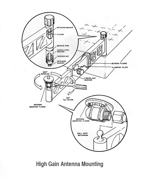
| Technical illustration of the mounting hardware installed on the front of the Rover before launch from Earth. During the mission, the astronauts could fit the high-gain staff to the mounting hardware without bending down. An Apollo 15 video clip shows Dave Scott installing the high-gain. |
Early Concept for LCRU operations during a traverse
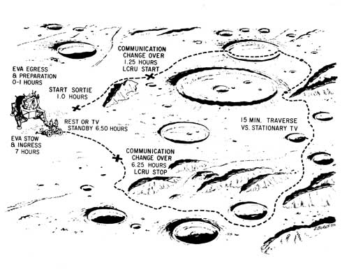
| This diagram appears to be a presentation of LCRU operations during a traverse, under the assumption that the LCRU would be on for most of the traverse. It is assumed that the crew gets out of the LM and spends about an hour preparing. About 15 minutes after they leave the LM, they will "start" the LCRU so they can communicate using the Rover antennas rather than going through the LM and, possibly, transmit TV continuously. It is not clear to me what is meant by the words "15 Min. Traverse vs. Stationary TV" on the righthand side of the drawing. At 5 hours of LCRU operation, they would "stop" using the LCRU and arrive at the LM about 15 minutes later. |
LCRU Pitch-Roll Indicator Concept
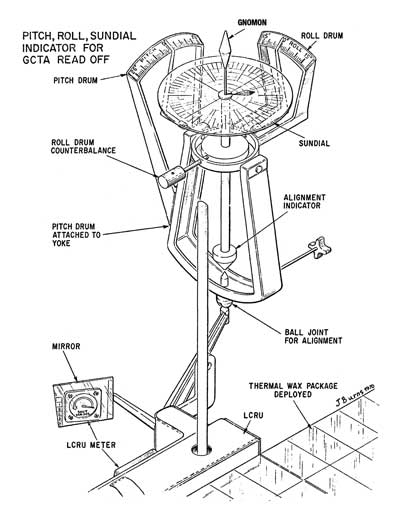
| Concept for a Pitch, Roll, Heading Indicator Mounted on the LRCU and intended for reading with the Ground Controlled Television Assembly (GCTA). Note, also, a mirror mounted to give a view of the signal strength meter on the side of the LCRU. The indicator may have been intended for use while the Rover was in motion. However, experience during Apollo 15 showed clearly that it wasn't possible to maintain high-gain pointing accurate enough while moving. A simpler Pitch/Rolll indicator was actually used on the Moon, mounted on the side of the Rover console in easy sight of the Commander. The Rover navigation system provided heading information based on differential wheel rotations since the last initialization. |
LCRU Options if the LRV isn't available
| A possible option if,
for example, development of the Rover had been
delayed long enough for NASA to fly a second MET
mission, as had been the original plan for Apollo
15. Although the terrestrial weight of the TV/TCU,
LCRU, batteries, and antennas was 48 kg and wouldn't
have overloaded the MET, the TV gear took up enough
room that the crew may have needed a second MET to
carry geology tools and samples. The
small box with handles mounted at the back is an
LCRU battery (approx. 12 x 24 x 12 cm, 4 kg). |
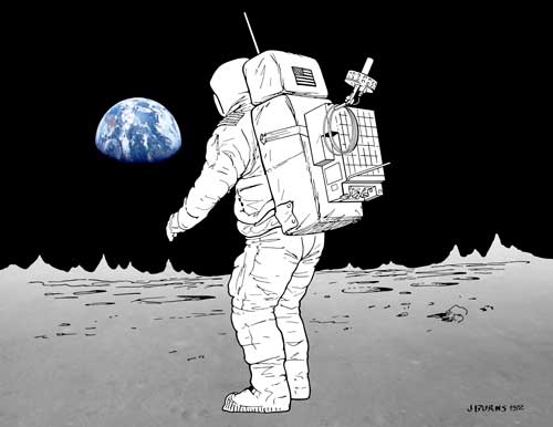
| In hindsight, this back-up plan for carrying the LCRU and low-gain antenna on one of the PLSSs probably wouldn't have been necessary. During Apollo 17 EVA-2, Gene Cernan and Jack Schmitt made a stop for a gravimeter reading on their way from Station 2 to Station 3. Gene noticed that he had forgotten to re-aim the low-gain when they left Station 2, meaning they had been communicating with Houston via a signal from Gene's PLSS antenna to the LM and onward to Earth, rather than via the low-gain. Despite the fact that they were over 7 km from the LM and without a line-of-sight to the spacecraft because of terrain on the Lincoln-Lee scarp, there is no noticeable difference in the recorded communications during this traverse segment compared with other periods when their comm was going directly to Earth via the low-gain antenna. |
Another Use for the High-Gain Antenna
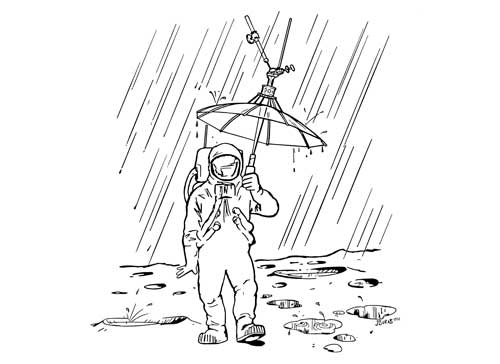
| Jim writes: "When the RCA team would go to Houston for proposal presentations or design reviews, I would slip in one or two humorous vuegraphs without mentioning it. NASA and our engineers loved it. They said it helped make the presentations more relaxing. |
Apollo 17 Surface Electrical Properties (SEP) Experiment
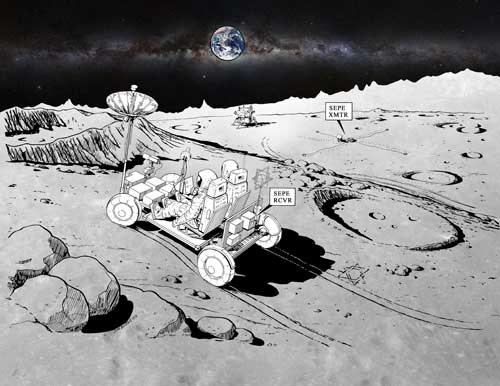
| Late in the their first EVA, the Apollo 17 crew deployed the SEP transmitter about 100 meters east of the LM, laying out a crossed-dipole antenna consisting of four 35-m long wires on a cross pattern of Rover tracks Gene Cernan made for that purpose. During the EVA-2 and EVA-3 traverses, the SEP recevier mounted at the back of the Rover recorded signals from the transmitter which ultimately yielded data about the properties of the rocks making up the upper few kilometers of the Moon. Note that this diagram uses an early acronym, SEPE, that included a final 'E' for 'Experiment'. |
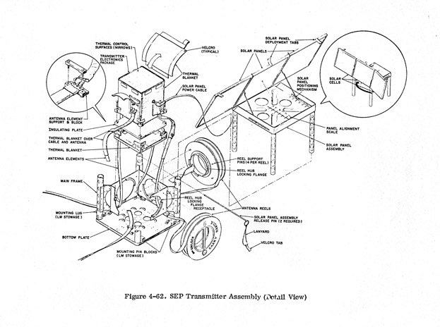
| A red-blue stereo-view of the SEP tranmitter from the back has been created from frames AS17-141-21510 and 511 by Erik van Meijgaarden. |
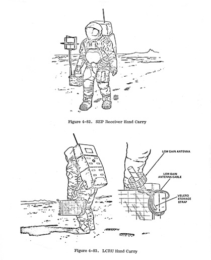
| It is possible to imagine that, had the Apollo 17 Rover failed, the crew might have hand carried the SEP receiver on the outbound leg of one of their walking traverses. As was done with the Rover traverses, they would have walked as far from the LM as they were going to go without doing much sampling, leaving the sampling for the walk back to the LM. This would have been done to maximize the consumables - oxygen and cooling water - they had available at their greatest distance from the LM. On the way back, sampling would have been the highest priority and they would have left the SEP receiver at the farthest point. |
Concept for Unmanned, Remote Control Use of the Rover
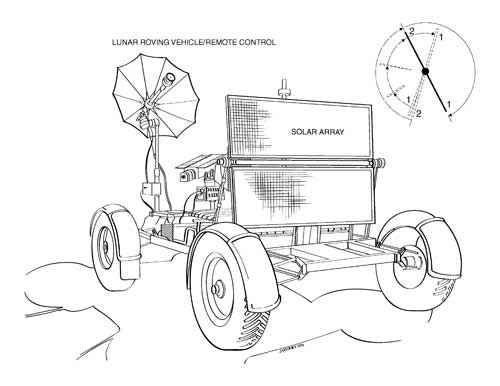
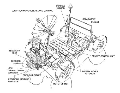
| Two views of a modified Rover equipped with solar panels for remote operation after the crew has returned to orbit. The seat backs and after payload have been removed to make way for the solar panels. A remote control box has been placed on the floor on the Commander's (lefhand) side. |
More Humor

| Proposal Deadline |
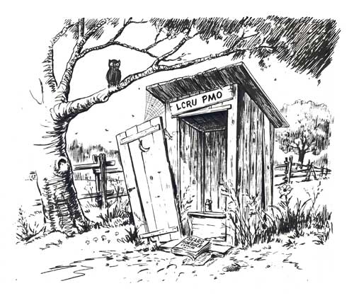
| Where the Program Management Office sends sinners. |
Other Works
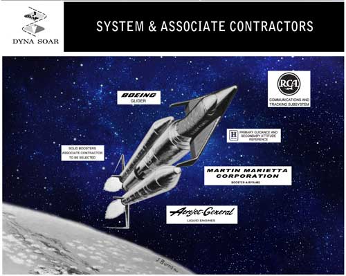
| Dyna Soar was a US Air Force Project to develop a space plane suitable for military purposes. It ran from 1957 to 1963. |
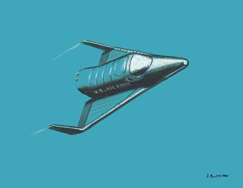
| DynaSoar Re-Entry Vehicle. |
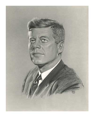
| Jim writes "This is a carbon pencil and charcoal portrait I created of President John Kennedy who was instrumental in kicking off the Apollo program." |
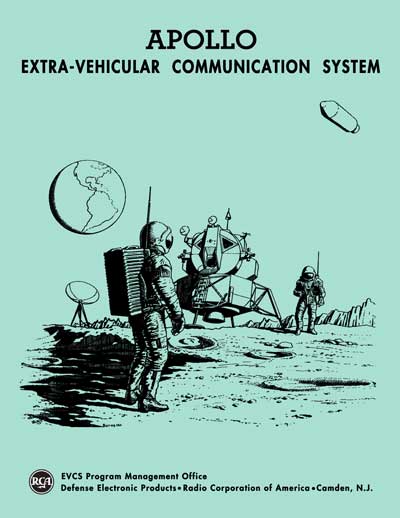
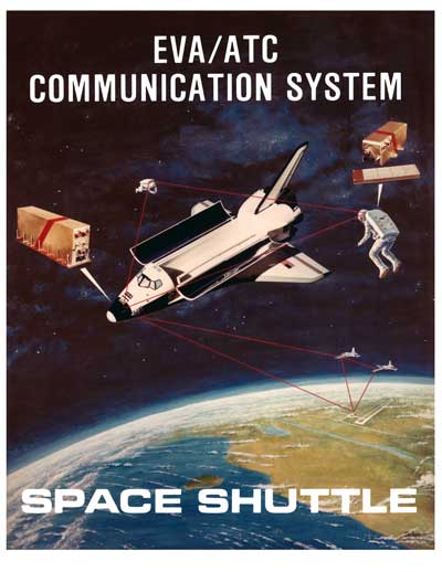
| "This is the cover to a proposal for the Extra-Vehicular Communication System in the early 1960's. Note the old RCA logo and the depiction of astronauts on the moon, a few years before this historic event happened." The RCA logo was changed in 1968. The LM depicted on this cover has triangular windows, which became a feature of the LM design in 1963; and a round hatch, which Grumman replaced with a square hatch at the insistence of astronaut Roger Chafee at the time of an October 1964 design review (Thomas J. Kelly, Moon Lander, 2001, p93). |
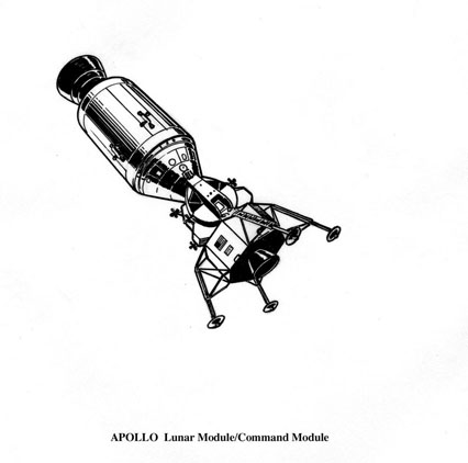
| Docked configuration prior to LM separation. |
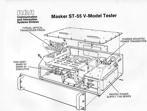
| "This is one I did for some long forgotten government project. I include this to show what type of work I spent most of my time on. I did hundreds of exploded and semi-transparent views but what I enjoyed doing most was conceptual illustrations." |
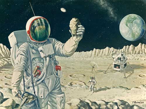
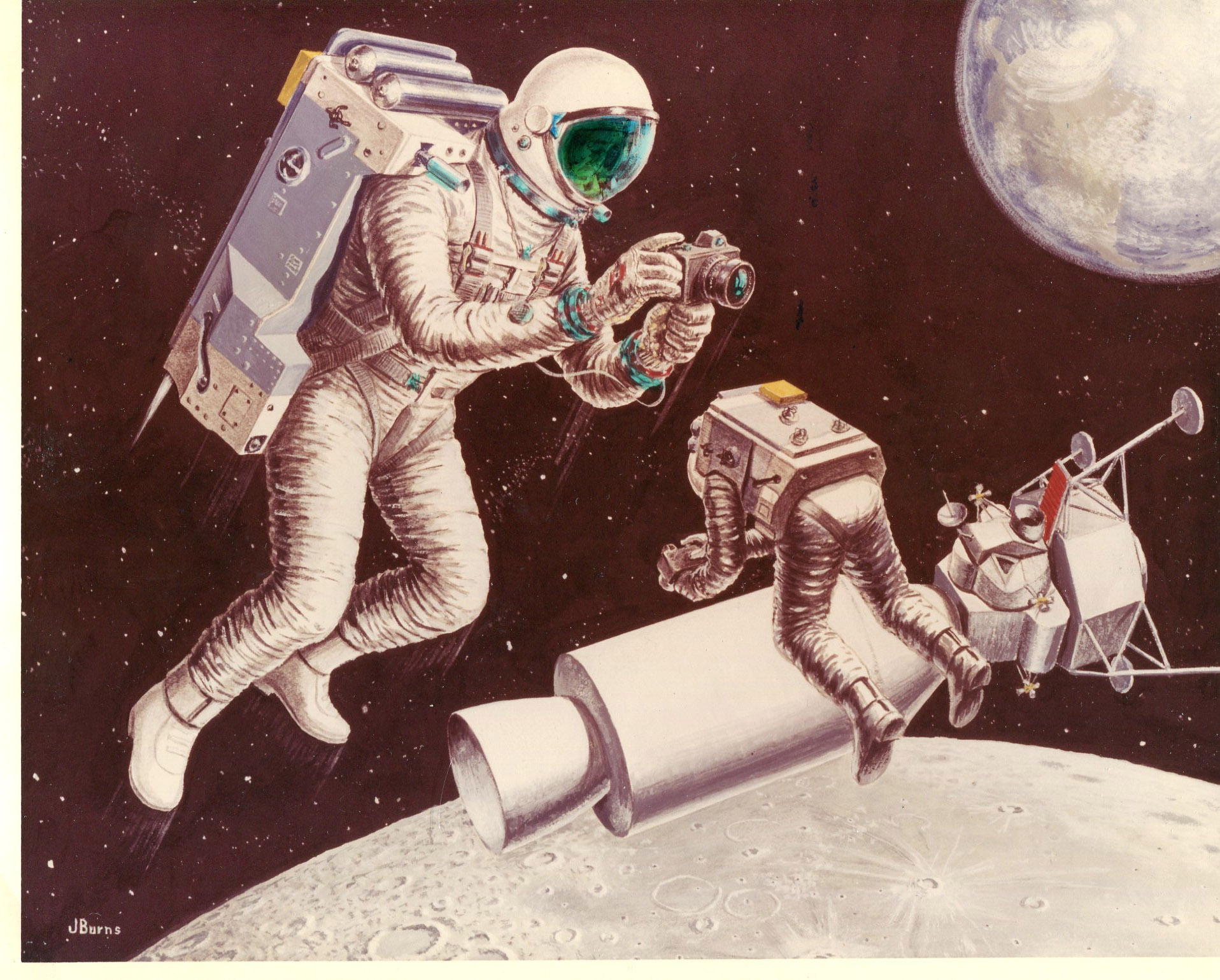
| This depiction of two astronauts collecting rock samples is interesting for both its realistic elements and for obvious applications of artistic license. |
| Communications
concepts for Shuttle EVA. |
James T. Burns
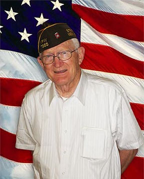
Mr. Burns, a veteran of World War 2 was awarded the Purple Heart and Bronze Star medal while serving with the 82nd Airborne Division. He began his working career shortly after being discharged. Jobs were scarce at the time and he signed on as an ordinary seaman in the Merchant Marine aboard an Atlantic Refining Company oil tanker. After a short time he enrolled in flight school under the G.I. Bill and earned his wings with a land and seaplane rating. Four years later he acquired a British Pilots license. After Flight School he worked for the Pennsylvania Railroad in track maintenance and later as a Block Operator in the Signal Department. From there he was hired as a Truck Traffic Supervisor at PublickerÂ’s Continental Industries.
In 1950 he went to England to study commercial art at the Chelsea Institute of Art in London for a year. After that he was hired by the US State Department Foreign Service as a staff member at the Embassy in London. He got married in England and after three years in London he and family were transferred to the US Embassy in Athens, Greece for two years and then to Washington DC for another year at the State Department. He then accepted a position with the Naval Air Engineering Facility in Philadelphia.
Mr. Burns has a natural born talent for drawing and painting but did not take up art as a vocation until during his time with Naval Air Engineering. He was asked to illustrate an engineer recruitment brochure plus a couple of other training programs and was awarded a Superior Accomplishment Award by the Naval Department. He was then recruited into the Engineering Department as a Technical Illustrator.
After three and a half years at the Naval Base he received an offer from RCA Government Systems Division who had seen some of his work. RCA offered a substantial increase in salary and he accepted. He worked there as an illustrator, with top secret government clearance, for twenty-nine years on various programs for the Air Force, Army, Navy, and NASA doing technical drawings, cut-away and exploded views, as well as full color concepts. Occasionally RCA corporate headquarters in New York would have him do charcoal portraits of company executives for testimonials.
After
retiring from RCA/GE in 1989, he was hired by American Systems
Engineering Corp., Virginia Beach, VA. to work at their
Philadelphia office as a technical illustrator on shipboard
installation contracts for the US Navy. After six years with
Amsec the company closed its Philadelphia office and Mr. Burns
was hired by another firm, a hair replacement company, as
their art director to design all their brochures, literature,
and magazine advertisements and negotiate printing costs with
various printing companies and mailing houses. This company
sent him to England for ten days to visit similar firms, study
their procedures, and to negotiate affiliations with those
that met company standards.
ALSJ Editor's note: My thanks to Alan Scalone, whose father, Sam, was a contract engineer/draftsman at RCA from late 1970 to September 1971 who worked on the mechanical engineering designs for the two LRV antenna masts. A number of drawings in his father collection of memorabilia were signed by "J Burns". Alan was able to locate Jim and then got Jim and me together by e-mail. This page is the result of that introduction.