
| Journal Home Page | Apollo 14 Journal | ALSEP Offload |
| Journal Home Page | Apollo 14 Journal | ALSEP Offload |
Introduction
The Apollo 14 SEQ Bay pendulum is a simple - if unintended - demonstration of motion in lunar gravity. There are many other cases such as John Young's two jumps during the Apollo 16 flag deployment, the sprays of dust kicked by the astronauts as they moved around the Moon, and the motion of thrown objects. However, in the case of the Apollo 14 pendulum, we are able to define the relevant parameters with far greater precision than in the other cases and have nearly one and a half minutes of well-defined, continuous motion available for study.
Journal Contributor Mike Craig notes that the Apollo 14 pendulum is an example of an Interrupted Pendulum, first describe by Galileo in 1638. Additional discussion and videos can be found via a web search for 'interrupted pendulum'. Because of the simplicity of the configuration, students and teachers can easily create a mock-up of the SEQ Bay pendulum at home or in the classroom and learn a great deal about differences between terrestrial gravity and lunar gravity.
Bogdan Tyburczy has filmed such a demonstration and provides insightful comparisons with the Apollo 14 video ( 86 Mb mpg film ). The Data
RealVideo Clip by Ken Glover, with thanks to Mark Gray ( 2 min 18 sec )
The clip starts at about 115:09:13 during the ALSEP Offload. Ed has just used the pulley system to extract the second ALSEP package from the righthand SEQ (Scientific Equipment) Bay and lowers the package to the surface. At about 115:10:36, he releases a tape that promptly swings under the spacecraft. A couple of seconds later, the tape reappears, retracing its path, and goes on swinging back and forth for nearly one and a half minutes before Ed disturbs it during the course of his work and the oscillations stop.
Ken Glover (KG) and I (EJ) independently timed the oscillations, noting when the tape goes through vertical from the left on its way back under the spacecraft. The following table gives the times relative to the initial passage thru vertical, which we call vertical number '0'. The intervals between successive vertical passages - the period - are given in the third column. Because the effective framing rate of the TV color-wheel system was 10 frames-per-second (see note below), the uncertainty in the times relative to first vertical passage is necessarily about 0.1 seconds. Each period, being the difference of the times of two successive vertical passages, is uncertain by about 0.2 seconds.
| Vertical No. | EJ-Time | KG-Time | EJ-Period | KG-Period |
| 0 | 0.00 | 0.00 | - | - |
| 1 | 4.95 | 5.07 | 4.95 | 5.07 |
| 2 | 9.95 | 9.97 | 5.00 | 4.90 |
| 3 | 14.85 | 14.84 | 4.90 | 4.87 |
| 4 | 19.65 | 19.74 | 4.80 | 4.90 |
| 5 | 24.50 | 24.44 | 4.85 | 4.70 |
| 6 | 29.25 | 29.24 | 4.75 | 4.80 |
| 7 | 33.95 | 34.00 | 4.70 | 4.76 |
| 8 | 38.85 | 38.77 | 4.90 | 4.77 |
| 9 | 43.45 | 43.50 | 4.60 | 4.73 |
| 10 | 48.25 | 48.20 | 4.80 | 4.70 |
| 11 | 52.95 | 52.94 | 4.70 | 4.74 |
| 12 | 57.70 | 57.60 | 4.75 | 4.66 |
| 13 | 62.40 | 62.30 | 4.70 | 4.70 |
| 14 | 67.05 | 66.97 | 4.65 | 4.67 |
| 15 | 71.75 | 71.70 | 4.70 | 4.73 |
| 16 | 76.45 | 76.37 | 4.70 | 4.67 |
| 17 | 81.15 | 81.00 | 4.70 | 4.63 |
| 18 | 85.75 | 85.64 | 4.60 | 4.64 |
The sequence of periods is presented in the following graph.
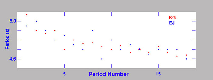
As we discuss below, this result is consistent with the configuration of the tape and SEQ Bay.
[Note: Both the Westinghouse and RCA color systems used during Apollo operated at 30fps but, because of the color wheel, it took three frames to complete a full-color image. In the original format, one can see the separation of colors in successive images of fast-moving objects. Indeed, Ken used software that allowed him to examine the frames one by one and the uncertainty of his times is probably about 0.033 seconds and his periods are probably good to about 0.067 seconds. The vertical scatter of his points is smaller than for mine.]For those wishing to jump directly to the conclusions, click here.
A Simple Pendulum
A simple pendulum consists of a nearly weightless string attached at an upper pivot point and, at the bottom, to weight sufficient to keep the string taut. If the length of the string is 'L' and the gravitational acceleration is 'g', the period 'P' is given by
P = 2π * SQRT ( L / g )On Earth, g = 9.81 meters per second per second and, on the Moon, g = 1.62 meters per second per second.
The Apollo 14 pendulum is not a simple pendulum for two reasons:
(1) Because of the SEQ Bay structure below the attachment point, the effective length of the pendulum is shorter when the end of the tape is under the spacecraft than when it is not.As we will see, these factors complicate the analysis, but not to a signficant degree.(2) There doesn't appear to be any attachment hardware visible on the bottom end of the tape. Although there is probably a clip of some sort, much of the tension in the tape may comes from its own weight. We can see an effect of this during the early, outward swings when the end of the tape flips upward, slightly, before starting back down.
SEQ Bay Configuration
A detail from Apollo 12 photograph AS12-46-6783 shows Al Bean pulling ALSEP package 2 away from the SEQ Bay. The tape of interest runs diagonally upward from near Al's right hand to an attachment point near the inner end of the boom.
A detail from Apollo 12 photograph AS12-46-6785 shows the tape after Al released it. Note that the portion below the bottom edge of the SEQ Bay (point B) appears to have gone past vertical and that this tape, like its Apollo 14 counterpart, is swinging. Unfortunately, we have no TV of the Apollo 12 ALSEP offload.
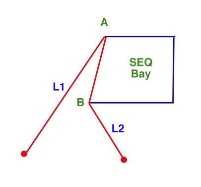
A second feature of the detail from 6785 is that, when the lower part of the tape is under the spacecraft, the upper part between point B and the upper attachment point A is is not perfectly vertical for the simple reason that point B is not directly below A. The configuration is shown in the following sketch.
Tape Lengths
In order to estimate L1 and L2, we need to know one or more other lengths in the available pictures. One 'ruler' is Al Bean himself but, because he is closer to the camera in 6785 than is the tape, it would be more reliable to use the dimensions of the SEQ Bay, which can be obtained from unflown LMs.
Grumman built Lunar Module Test Article LTA-1 in 1963 after winning the LM contract. LTA-1 currently resides at the Cradle of Aviation Museum on Long Island, New York.
Frank O'Brien writes, "LTA-1 was the engineers' 'sandbox' to play in. It really became a 'mutt' (mixed-breed), rather than being a 'purebreed', and its evolution reflects how the LM itself evolved. In the picture of the ascent stage, you'll see it is of the 'round hatch' variety. On the descent stage, however, it has all the J-mission items of interest - the larger fuel tanks, the larger MESA, and Rover attachment points."
"LTA-1 was probably constantly modified, and items that did not directly support the current testing or round of changes were left in place. Also, it's not surprising that lots of the weight reduction changes made in the production LMs were not included in LTA-1, probably because of the amount of rework that would have been needed. Strain and temperature sensors are located throughout the structure, reflecting LTA-1's role in dynamic testing."
Frank and Stacey O'Brien took a number of photos and measurements of the LTA SEQ Bay relevant to the pendulum analysis:
LTA-1-SEQ-01 shows the two-compartment SEQ Bay from the right side. Frank writes, "Note the small volumes of the compartments. The inverted 'V' structures are part of the 'dummy masses' used to simulate the presence of ALSEP packages during dynamic testing. No doors are in place, but the ratchet wheels for the tapes used to lower the packages are there. It is unclear what the function is of the yellow brackets at the bottom of the bay, although they are certainly not part of the dummy masses. I'm standing approximately where the minus-Z strut would be." Apollo 12 counterparts of the yellow brackets are labeled in the detail from AS12-46-6785. There are numerous other similarities.LTA-1-SEQ-03 shows more detail of the lower lip of the righthand compartment. I have not been able to identify a part of the LTA-1 structure that corresponds exactly to point B in 6785. A comparison suggests that the vertical position of B is close to that of the lower edge of the horizontal yellow band in the LTA photo, as indicated by the red line drawn on the image.
LTA-1-SEQ-14 shows that the two yellow brackets at the bottom of the righthand compartment are centered 17 inches (0.43 m) apart.
LTA-1-SEQ-17 shows that the compartment is 23 inches (0.58 m) deep.
LTA-1-SEQ-20 shows that the yellow brackets are 6 inches (0.15 m) long.
LTA-1-SEQ-21 shows inner height of the compartment is about 21 inches (0.53 m).
LTA-1-SEQ-23 shows that the distance from the top of the structure (approximating the vertical location of the tape attachment point A) to the bottom of the horizontal yellow band (approximating B) is about 25 inches (0.64 m).
Although there are many similarities and some obvious differences getween the LTA-1 SEQ Bay and the one flown on Apollo 12, the overall dimensions seem much the same. Frank writes, "I suspect that, with regard to the SEQ Bay, LMs 3, 4, 5, 6 were all similar in size to the one we find on LTA-1. If so, it is another example of how a design gets created, and then 'abandoned in place'."
Using the LTA-1 photos and measurements, we can estimate that point B in our sketch is 25 inches (0.64 meters ) vertically below A and is displaced 6 inches (0.15 m) horizontally. Consequently, the length of tape between A and B in AS12-46-6785 is about 0.7 meters and that the length of tape hanging below B is about 0.9 meters.
Consequently, in the following analysis, we will use L1 = 0.7 + 0.9 = 1.6 meters and L2 = 0.9 meters. Both numbers are uncertain by about 0.1 meters.
On the Moon, pendula of these lengths would have periods of
P1 = 2π * SQRT ( L1 / 1.62 ) = 6.2 secondsand
P2 = 2π * SQRT ( L2 / 1.62 ) = 4.7 seconds.Because the lengths are uncertain by 0.1 meters, the periods are uncertain by about 0.2 seconds. On Earth, the two periods would be 2.5 seconds and 1.9 seconds respectively, with an uncertainty of 0.1 seconds.Two-Mode Pendulum without Offset
Because the effective length of the Apollo 14 pendulum changes when the weight goes under the spacecraft, it is not a simple pendulum. However, it can be understood as follows. The full period can be divided into two parts. During the first part, when the tape is on the left, the effective length of the pendulum in L1. During the second part, when the tape is on the right and under the SEQ Bay, the effective length of the pendulum is L2. For the moment, let us consider the case where point B is directly below A. As can be demonstrated by experiment at home or at school, the period of this pendulum is
P = 0.5 * ( P1 + P2 ) = π * ( SQRT ( L1 / g ) + SQRT ( L2 / g ) )no matter what lengths L1 and L2 are used.Experimental check: I screwed an "eye" into a ceiling beam in my study and hung a length of thread with a small weight tied at the bottom. I measured the length of the pendulum and got L1 = 1.385 m which, when combined with g = 9.81 m/s/s gives an expected period of P1 (expected) = 2.361 seconds. I timed sequences of fifty periods several times with the stopwatch feature on my wristwatch and got an average of P1 (measured) = 2.358 seconds, which is quite satisfacory agreement.
I then brought in a ladder and a long piece of wood (square cross-section about 2 cm by 2 cm) and fixed one end on the top of the ladder other end on the top of a picture frame (an Al Bean print, of course) so that the piece of wood would catch the string directly below the "eye". I measured the length of the string section hanging below the piece of wood and got L2 = 0.815 cm. This gives an expected value of P2 (expected) = 1.811 seconds and P (expected) = 0.5 * ( P1 + P2 ) = 2.086 seconds. Again, I measured fifty periods several times and got an average of P = 2.090 seconds. Again, excellent agreement.
As long as B is directly below A, the formula P = 0.5 * ( P1 + P2 ) is valid for any combination of L1 and L2. For the sake of discussion, let's consider a fixed value for L1 and think about what happens as we put point B at various distances below A and, thereby, vary L2.
Consider, first, what happens as we move B upward toward A. Clearly, L2 increase toward L1 and, in the limit where B is coicident with A, we would have L2 = L1. We would also have P2 = P1 and
P = 0.5 * ( P1 + P2 ) = P1 .In other words, as B gets closer to A, the system behaves more and more like a simple pendulum of length L1.For our second thought experiment, let us consider about what happens as point B moves downward toward a distance L1 below A. As B moves down, L2 approaches zero and the time spent on the righthand side ( P2 ) also decreases toward zero. In the limit where P2 = 0, we have
P = 0.5 * ( P1 + P2) = 0.5 * P1 .In essence, we have a simple pendulum of length L1 that 'bounces' off B and completes only half a period on each swing.To illustrate let us consider a widely available science toy - usually called a Newton's Cradle - which consists of a framework from which a number of steel balls are suspended in a line by pairs of threads so that the balls are just touching or close to touching their neighbors. In the usual demonstration, one of the end balls is raised and then released. Once it strikes the first stationary ball, the collision is transmitted down the line and, almost without delay, a single ball flies up from the opposite end, and so on. If, however, we raise one ball at each end and release them simultaneously, they strike the line of stationary balls simultaneously and, almost immediately, fly back out again. From a practical perspective, the period is halved.
Two-Mode Pendulum with Offset
If, as in our Apollo 14 sketch, point B is offset laterally to the left from directly beneath A, the pendulum will spend more of its time in the shorter period mode and less in the longer period mode. In other words, the overall period will be closer to P2 than to P1. (If B were displaced to the right, the overall period would be closer to P1 than to P2.) The degree of period offset will depend on several factors, including the lateral displacement of B, the two lengths, L1 and L2, and the maximum amplitude of the pendulum.
To illustrate, let us consider the case where we raise the pendulum to the left until the string is just about to lose contact with point B. If we then release the pendulum, the string will never leave contact with B, the pendulum length will always be L2 and its period will always be P2. If, however, we release the pendulum from a point farther to the left, the pendulum will spent at least a little time in the longer period mode and we will have an overall period greater than P2.
To complicate matters a bit more, there are energy losses in any real pendulum due to friction and other factors (see the discussion below) and the amplitude will decrease slightly with each successive swing. Therefore, if we release the pendulum at some point well to the left so that the string is not touching point B at the start, after enough swings back and forth, the amplitude will decrease to the point that the string stays in constant contact with B. At the beginning, the overall period of the pendulum will start out being somewhat larger than P2 but will decrease until it reaches P2.
To test this line of thought, I set up a pendulum in my study once again. I still had the string, weight, and eye from the first trial and, therefore, had L1 = 1.385 meters and P1 (expected) = 2.360. As a test, I timed four series of 40 periods each and got an average of 2.366.
Next, I used the same piece of wood (with a 2 cm by 2 cm square cross-section), but this time secured it to the top of the door and to a curtain rod. As a test, I placed the piece of wood directly below the eye. This configuration gave L2 = 0.963 meters, P2 (expected) = 1.968 seconds, and P (expected) = 0.5 * ( P1 + P2 ) = 2.164 seconds.
Because the amplitude was going to decay, I timed three series of 5 periods, three series of 10 periods, three of 15 periods, and three of 20 periods to see if the later periods were significantly different from the earlier periods. For all the timings, I released the pendulum from a point 0.645 meters to the left of the vertical plane through A and the piece of wood. At the moment of release, the string was 28 degrees from vertical.
The times required to complete a given number of periods are given in the following table:
Number
of
PeriodsTotal Time to Complete Average High Low 5 11.00 11.11 10.94 10 21.75 21.83 21.64 15 32.65 32.72 32.57 20 43.55 43.51 43.58 Taking differences between the average times to completion, we get the average periods given in the following table:
Period Nos. Interval Average
Period0-5 0 - 11.00 2.20 6-10 11.00 - 21.75 2.15 11-15 21.75 - 32.65 2.18 16-20 32.65 - 43.55 2.18 None of these averages differs signficantly from P (expected) = 0.5 * ( P1 + P2 ) = 2.164 seconds.
Next, I displaced the piece of wood 0.11 meters to the left. This increases the length of string above B slightly, and gives L2 = 0.940 meters and P2 (expected) = 1.944 seconds. As a test, I ran two series of twenty periods with the release point being such that the string never left contact with B. The average periods for these two runs were 1.950 and 1.954 seconds, both in satisfactory agreement with the expected value.
Next, I did a six series each of 4, 8, 12, 16, 20, and 32 periods, releasing the pendulum on each series from the point 0.645 meters to the left of the vertical line passing thru A. As mentioned previously, at the moment of release, the string was about 28 degrees from vertical. When the string is about 15 degrees from vertical, it makes contact with B.
I did not count the first period and started timing when the pendulum reached its farthest left point for the second time. This eliminated uncertainty in getting my stopwatch function started. Note, also, that in each of the 32 periods series, the amplitude decayed in such a way that the string was always in contact with B at about period 20.
The times required to complete a given number of periods are listed in the following table:
Number
of
PeriodsTotal Time to Complete Average High Low 4 8.21 8.30 8.08 8 16.30 16.12 16.45 12 24.34 24.20 24.49 16 32.35 32.15 32.47 20 40.25 40.02 40.44 32 63.96 63.87 64.02 Note that the spread in values is larger than in the case with B below A, suggesting that I wasn't being as consistent in operating the stopwatch function.
Taking the differences, we get the average periods listed in the following table:
Periods Interval Average
Period0-4 0 - 8.21 2.05 5-8 8.21 - 16.30 2.02 9-12 16.30 - 24.34 2.01 13-16 24.34 - 32.35 2.00 17-20 32.35 - 40.25 1.98 21-32 40.25 - 63.96 1.98 Clearly, even for the first four periods, the average period is much closer to P2 = 1.944 seconds than to P1 = 2.360 seconds.
As discussed above, the Apollo 14 pendulum has L1 = 1.6 meters and L2 = 0.9 meters. Both numbers are uncertain by about 0.1 meters. On the Moon, the periods associated with these lengths are P1 = 6.2 seconds and 4.7 seconds, respectively, with each being uncertain by about 0.2 seconds
As inferred from measurements made on LTA-1 and consistent with Apollo 12 photo AS-12-46-6785, point B in our sketch is 0.63 meters vertically below A and is displaced 0.15 meters horizontally. Consequently, when the tape is more than 13 degrees to the left of vertical, it is not in contact with B.
Examination of both Apollo 12 photo AS-12-46-6783 and the Apollo 14 TV suggests that the tape was released at an angle of about 45 degrees from vertical.
As discussed above, the fact that B is not directly below A but is displaced to the left, means that the pendulum period will start out somewhere between P2 = 4.7 seconds and 0.5 * ( P1 + P2 ) = 5.48 seconds, with the exact value depending on the initial displacement. Subsequently, if damping is important, the period will decrease until it becomes constant at 4.7 seconds.
As can be seen in the graph, the initial period (starting with passage thru first vertical from the left) is about 5.0 seconds. As the amplitude of the swings decrease, the period decreases until it reaches a steady value of about 4.7 seconds after about the tenth period.
As a final point, it is important to note that, in the experiments I ran in my study, air drag and air currents contributed to the decreasing amplitude of successive swing. On the Moon, which has virtually no atmosphere, the decrease in amplitude of the Apollo 14 pendulum is necessarily due to other factors. Looking carefully at the video clip, notice that, for the first several swings to the left, the tape does not remain straight, but that the tip flips up. This happens because there is relatively little weight at the bottom of the tape to keep it taut. This suggests a mechanism that would produce damping. Specifically, the 'flip' of the end of the tape will necessarily send wave-like disturbances up the tape and, at both B and A, flexing of the tape and/or tiny motions induced in the LM will dissipate energy. It seems significant that, by the time that the period reaches its steady value of 4.7 seconds, the 'flip' has virtually disappeared and, thereafter, the amplitude no longer decreases. In other words, whatever the precise mechanisms responsible for the observed damping, they are not signficant after about period 10.
I would be interested in getting the results of any experiments that readers undertake to understand details of the Apollo 14 pendulum.
Journal Home Page Apollo 14 Journal ALSEP Offload