
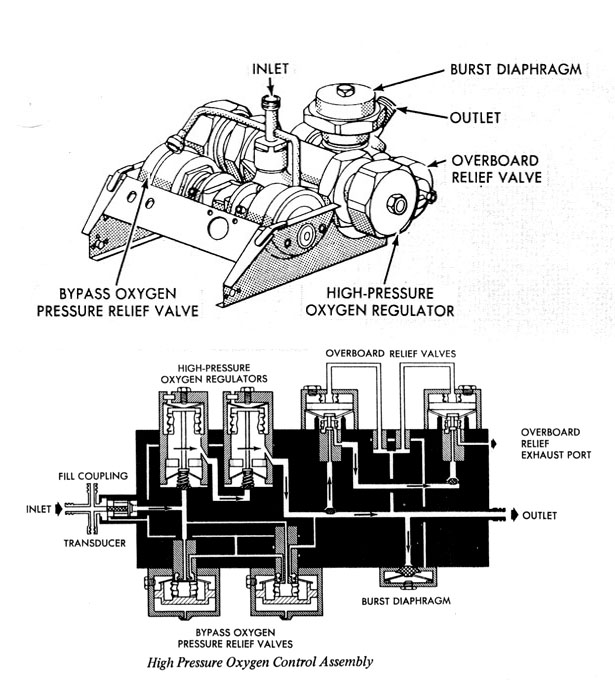
Bypass Oxygen Pressure Relief Valve The bypass oxygen pressure relief valve protects the descent oxygen tank against overpressurization by bypassing the high-pressure oxygen regulator. The valve is designed to fail in the open condition if it malfunctions. If the relief valve malfunctions (bellows ruptures), the valve is automatically placed in the failed-open condition, bypassing the oxygen to a secondary (identical) relief valve.
Overboard Relief Valve The series-redundant overboard relief valve vents oxygen to ambient when the pressure downstream of the high-pressure oxygen regulator reaches 1,025 psig. The valve is fully open at 1,090 psig and reseats at 985 psig at +75' F. The relief valve has a fail-open feature. If a capsule sensing element leaks, the oxygen is dumped into the leakage chamber and bleeds overboard.
Burst Diaphragm Assembly The burst diaphragm assembly opens when the flow from the descent oxygen tank exceeds the relieving capability of the overboard relief valve. An aluminum disk in the inlet port of the burst diaphragm assembly ruptures at a, system pressure between 1,300 and 1,400 psig. System pressure causes the diaphragm support to move away from the disk, causing it to rupture. The disk support poppet opens and vents the descent oxygen tank. The diaphragm assembly permits a minimum flow of approximately 10 pounds per minute. When descent tank pressure is reduced to 1,000 psia, the disk support poppet reseats to maintain sufficient oxygen for one cabin repressurization up to 1 hour after disk rupture.
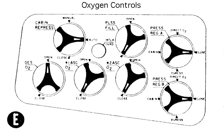
Oxygen Demand Regulators Two, parallel oxygen demand regulators regulate oxygen from the tanks to the suit circuit. Both regulators are manually controlled by individual four-position selector handles. Suit circuit pressure is fed back to an aneroid bellows that actuates a poppet. Rotating the valve handle to cabin or egress position changes the spring force acting on the poppet and establishes two outlet pressure levels. Selecting the direct 02 position, fully opens the valve. With an upstream pressure of 900 psia and a temperature of +70' F, one regulator can flow approximately 7.0 pounds per hour into the suit circuit. In the closed position, an auxiliary poppet stops all flow through the regulator. Each regulator has valve position indicator (VPI) switches, and two functional switches that control electrical circuits in the ECS.
Cabin Repressurization and Emergency Oxygen Valve The cabin repressurization and emergency oxygen valve is a solenoid-operated valve with manual override. It is used to repressurize the cabin after a deliberate decompression and provides an emergency flow of oxygen if the cabin is punctured. If the cabin is punctured and the diameter of the hole does not exceed 0.5 inch, the valve can maintain cabin pressure at 3.5 psia for at least 2 minutes, allowing the astronauts to return to a closed-suit environment. The cabin repressurization and emergency oxygen valve is controlled by a three-position handle on the oxygen control module.
When the automatic position is selected, valve operation is controlled by the solenoid, which is actuated by the cabin pressure switch. If either oxygen demand regulator is set to cabin or direct 02 positions and cabin pressure drops below normal, the cabin pressure switch energizes the solenoid. This moves the valve yoke to open the inlet valve and permits oxygen from the oxygen manifold to flow through the valve into the cabin. If cabin pressure increases to normal, the cabin pressure switch deenergizes the solenoid and spring action closes the valve. Setting both oxygen demand regulators to the close or egress positions disables the circuitry to the solenoid through the cabin pressure switch, provided suit pressure does not drop below 3.12 psia. When supplied by the descent GOX tank, flow is 4 pounds per minute maximum; when supplied by the ascent tank, 8 pounds per minute at 700 psia. When the manual position is selected, the handle shaft actuates a cam that moves the yoke to open the inlet valve and establish flow to the cabin. In the close position an auxiliary poppet is forced onto its seat, shutting off the flow.

Setting the internal handle to the dump position unseats -the poppet. The valve in the overhead hatch can dump cabin pressure from 5.0 to 0.08 psia in 180 seconds without cabin oxygen inflow; the forward hatch valve (with filter) in 310 seconds. Setting the handle to the closed position prevents the valve from opening at normal presSUres, if the servo valve fails.
The oxygen bacterial filter (flown only on Apollo 11) on the cabin side of the forward cabin relief and dump valve removes bacteria from the dumped cabin oxygen. The filter can be installed and removed by an astronaut in the cabin. It removes 95% of all bacteria larger than 0.5 micron.