
Note: The functional description of each of the four major ECS sections is supported by a functional flow diagram, which, to reduce complexity, does not contain electrical circuitry.
Note: The functional description of each of the four major ECS sections is supported by a functional flow diagram, which, to reduce complexity, does not contain electrical circuitry.
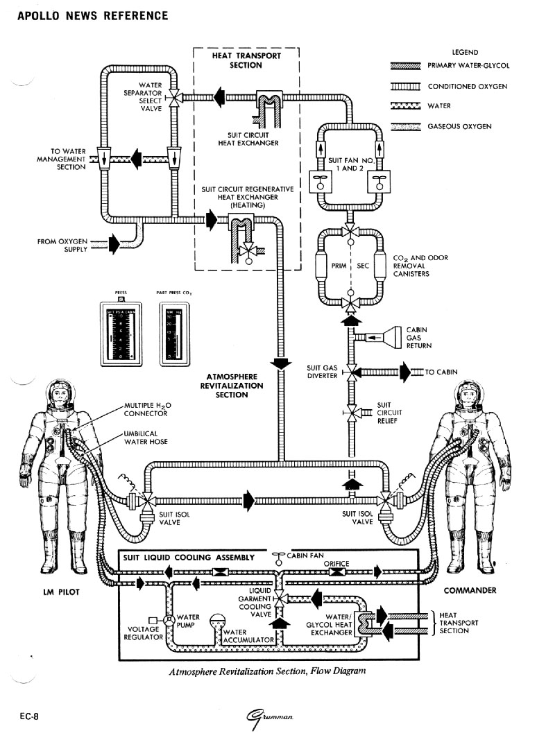
The CABIN position of the suit gas diverter valve ( 106k) is used during pressurized-cabin operation, to direct sufficient conditioned oxygen to the cabin to control carbon dioxide and humidity levels. Pulling the valve handle selects the EGRESS position to isolate the suit circuit from the cabin. The EGRESS position is used for all unpressurized-cabin operations, as well as closed suit mode with pressurized cabin. An electrical solenoid override automatically repositions the valve from CABIN to EGRESS when cabin pressure drops below the normal level or when the EGRESS position is selected on the pressure regulators.
With the suit gas diverter valve ( 106k) set to the cabin position, cabin discharge oxygen is returned to the suit circuit through the cabin gas return valve ( 159k). Setting the cabin gas return valve ( 159k) to automatic (AUTO) position enables cabin pressure to open the valve. When the cabin is depressurized, differential pressure closes the valve, preventing suit pressure loss.
A small amount of oxygen is tapped from the suit circuit upstream of the PGA (Pressure Garment Assembly) inlets and fed to the carbon dioxide partial pressure sensor, which provides a voltage to the C02 partial pressure indicator.
The primary and secondary carbon dioxide and odor removal canisters ( 159k) are connected to form a parallel loop. The primary canister contains a LM cartridge with a capacity of 41 man hours; the secondary canister, a PLSS cartridge with a capacity of 14 man hours. A debris trap in the primary canister cover prevents particulate matter from entering the cartridge. A relief valve in the primary canister permits flow to bypass the debris trap if it becomes clogged. Oxygen is routed to the C02 and odor removal canisters through the canister selector valve ( 159k). The carbon dioxide level is controlled by passing the flow across a bed of lithium hydroxide (LiOH); odors are removed by absorption in activated charcoal. When carbon dioxide partial pressure reaches or exceeds 7.6 rnm Hg, as indicated on the partial pressure C02 indicator, the C02 component caution light and ECS caution light go on. (The C02 component caution light also goes on when the C02 canister selector valve is in the secondary position.) The C02 canister selector valve ( 159k) is then set to the secondary position, placing the secondary canister onstream. The primary cartridge is replaced and the C02 canister selector valve is set to the primary position, placing the primary canister back onstrearn.
From the canisters, conditioned oxygen flows to the suit fan assembly, which maintains circulation in the suit circuit. Only one fan operates at a time. The ECS suit fan 1 circuit breaker is closed and the SUIT FAN selector switch is set to 1 to initiate suit fan operation. At startup, a fan differential pressure sensor is in the low position (low Δ P), which, through the fan condition signal control, energizes the ECS caution light and suit fan component caution light. The lights remain on until the differential pressure across the operating fan increases sufficiently to cause the differential pressure sensor to move to the normal position. If the differential pressure drops to 6.0 inches of water or less, the lights go on and switchover to fan No. 2 is required. The ECS caution light goes off when fan No. 2 is selected and the suit fan warning light goes on. The suit fan component caution light goes off when fan No. 2 comes up to speed and builds up normal differential pressure. The suit fan warning light and suit fan component caution light go off if fan No. 2 differential pressure reaches 9.0 inches of water. The fan check valve permits air to pass from the operating fan without backflow through the inoperative fan.
From the check valve, the conditioned oxygen passes through a sublimator to the cooling heat exchanger. The sublimator cools the oxygen under emergency conditions. Heat transfer to the coolant in the heat exchanger reduces gas temperature and causes some condensation of water vapor.
The conditioned oxygen is next routed to two parallel-redundant water separators through the water separator selector valve ( 159k). One separator, selected by pushing or pulling the water separator selector valve handle ( 159k), is operated at a time. The separator is driven by the gas flowing through it. Moisture removed from the oxygen is discharged under a dynamic head of pressure sufficient to ensure positive flow from the separator to the WMS. A water drain carries some water from the separators to a surge (collection) tank outside the recirculation system.
The conditioned oxygen from the water separator is mixed with makeup oxygen from the OSCPCS to maintain system pressure. The mixture flows through the regenerative (heating) heat exchanger, where the temperature may be increased, to the suit isolation valves ( 181k). The suit temperature control valve ( 136k) on the water control module controls the flow of coolant through the regenerative heat exchanger. Setting the valve to the increase hot position increases oxygen temperature; setting it to decrease cold position reduces the temperature.