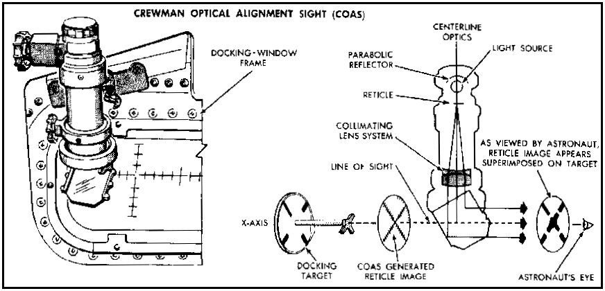
Crewman Optical Alignment Sight
Adam Bootle, Kipp Teague, Paul Fjeld, and David Woods contributed to this page.
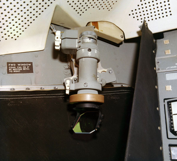
NASA photo KSC-69C-8237 shows the Apollo 12 COAS mounted in the Commander's window. The COAS projected a collimated image of an internal reticle on a nearly transparent 'combiner' angled at 45 degrees to that the image could be seen by the user. Transparency of the combiner also allowed the user to see the distant target and, because of collimation of the recticle image, the target and reticle image appear to the user to be at the same distance. The COAS could also be mounted in the LM overhead docking window. An identical instrument was available in the Command Module and a similar instrument is used by Shuttle crews.
COAS Description and Diagrams.
From the Apollo Lunar Module News Reference (1968).
Scanned and formated by Adam Bootle.

(Click on the image for a larger version.)
The COAS provides the Commander with gross range cues and closing rate cues during the docking maneuver. The closing operation, from 150 feet to contact, is an ocular, kinesthetic coordination that requires control with minimal use of fuel and time. The COAS provides the Commander with a fixed line-of-sight attitude reference image, which appears to be the same distance away as the target.
The COAS is a collimating instrument. It weighs approximately 1.5 pounds, is 8 inches long, and operates from a 28-volt d-c power source. The COAS consists of a lamp with an intensity control, a reticle, a barrel-shaped housing and mounting track, and a combiner and power receptacle. The reticle has vertical and horizontal 10-degree gradations in a 10-degree segment of the circular combiner glass, on an elevation scale (right side) of -10 degrees to +31.5 degrees. The COAS is capped and secured to its mount above the left window (position No. 1).
To use the COAS, it is moved from position No. 1 to its mount on the overhead docking window frame (position No. 2) and the panel switch is set from OFF to OVHD. The intensity control is turned clockwise until the reticle appears on the combiner glass; it is adjusted for required brightness.
Alignment and Simulation Images
COAS Alignment. NASA photo S68-44005.
Scan courtesy Jody Russell and Mike Gentry, NASA Johnson.
(Click on the image for a larger version.)
COAS Alignment. NASA photo S68-44005.
Scan courtesy Jody Russell and Mike Gentry, NASA Johnson.
(Click on the image for a larger version.)

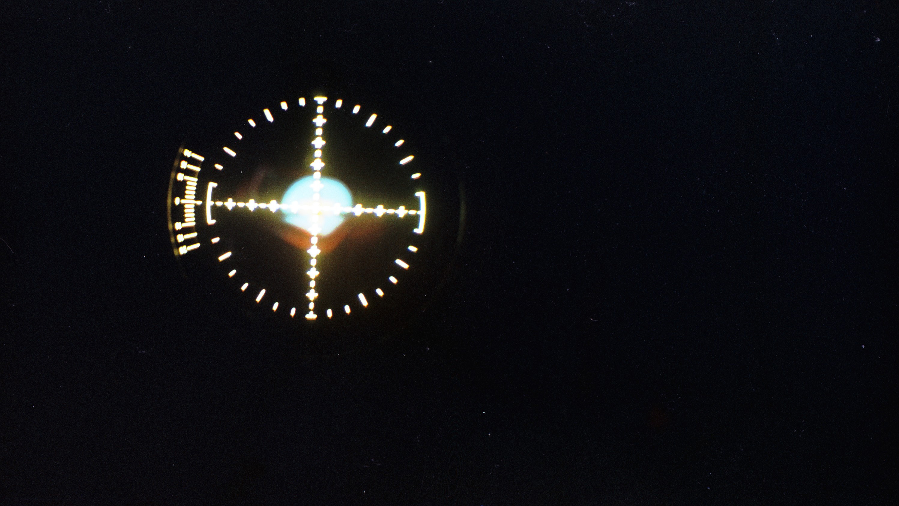
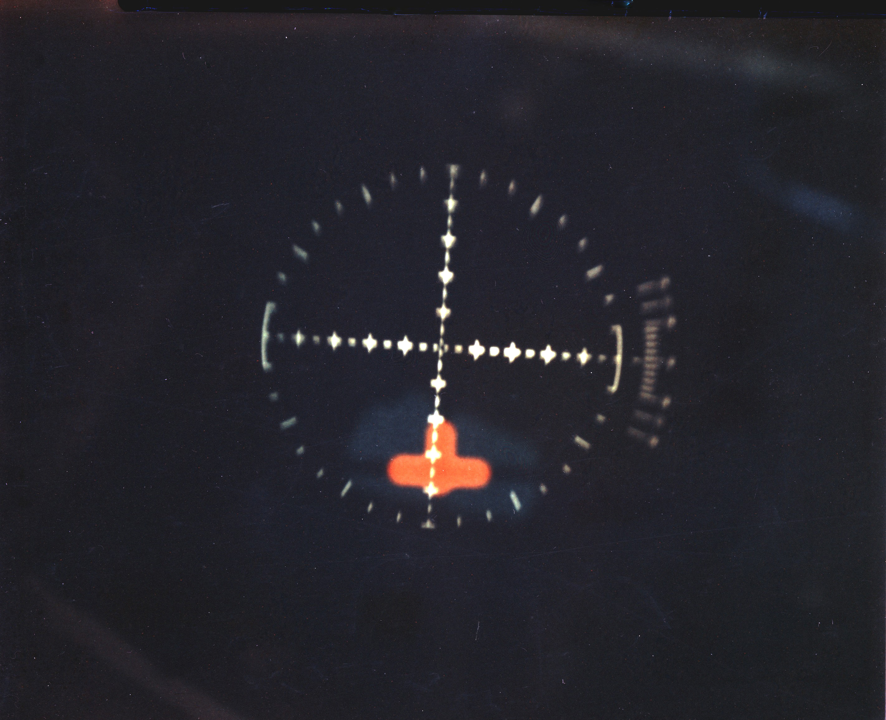
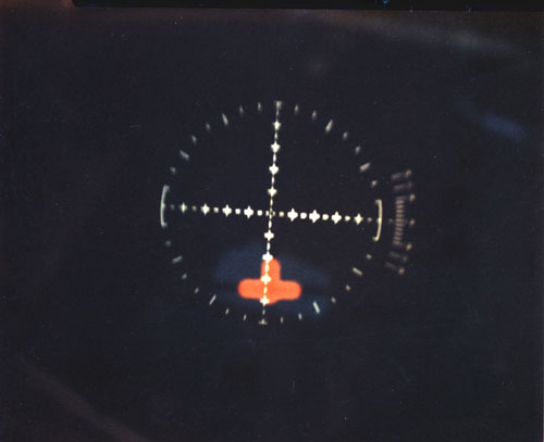
NASA Caption: Simulated views of the docking process
as seen by the Astronaut through the COAS (Crew Optical Alignment Sight).
NASA photo S69-28912.
Scan courtesy Jody Russell and Mike Gentry, NASA Johnson.
(Click on the image for a larger version.)

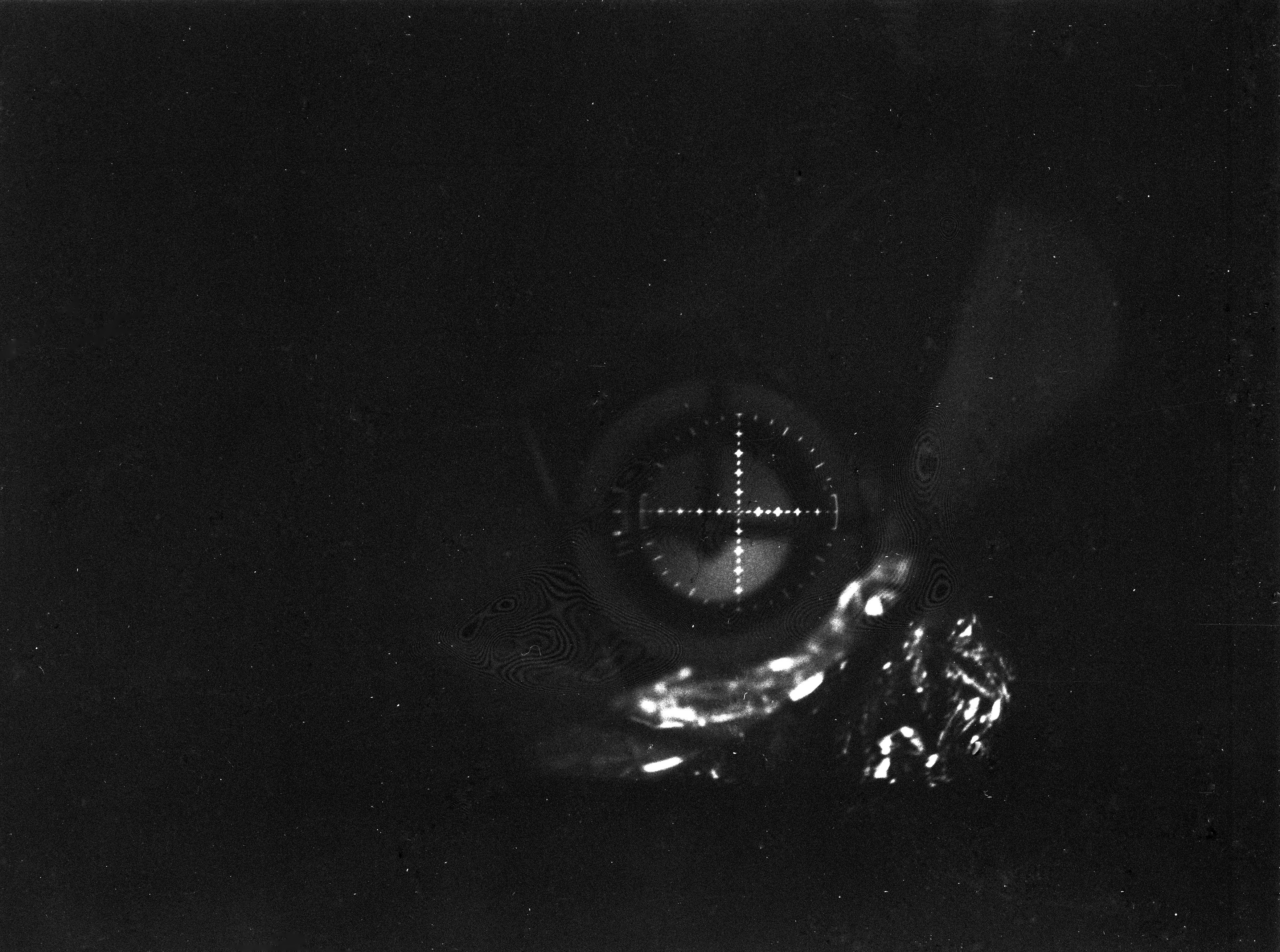
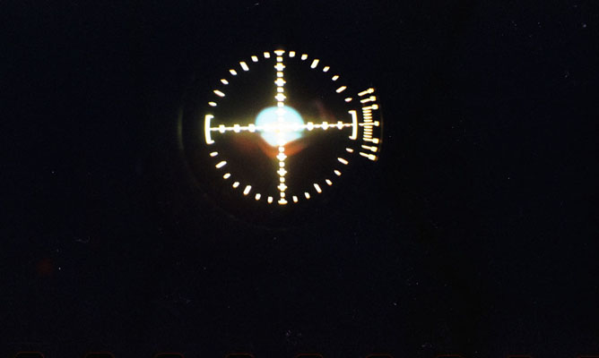
NASA Caption: Simulated views of the docking process
as seen by the Astronaut through the COAS (Crew Optical Alignment Sight).
NASA photo S69-28913.
Scan courtesy Jody Russell and Mike Gentry, NASA Johnson.
(Click on the image for a larger version.)
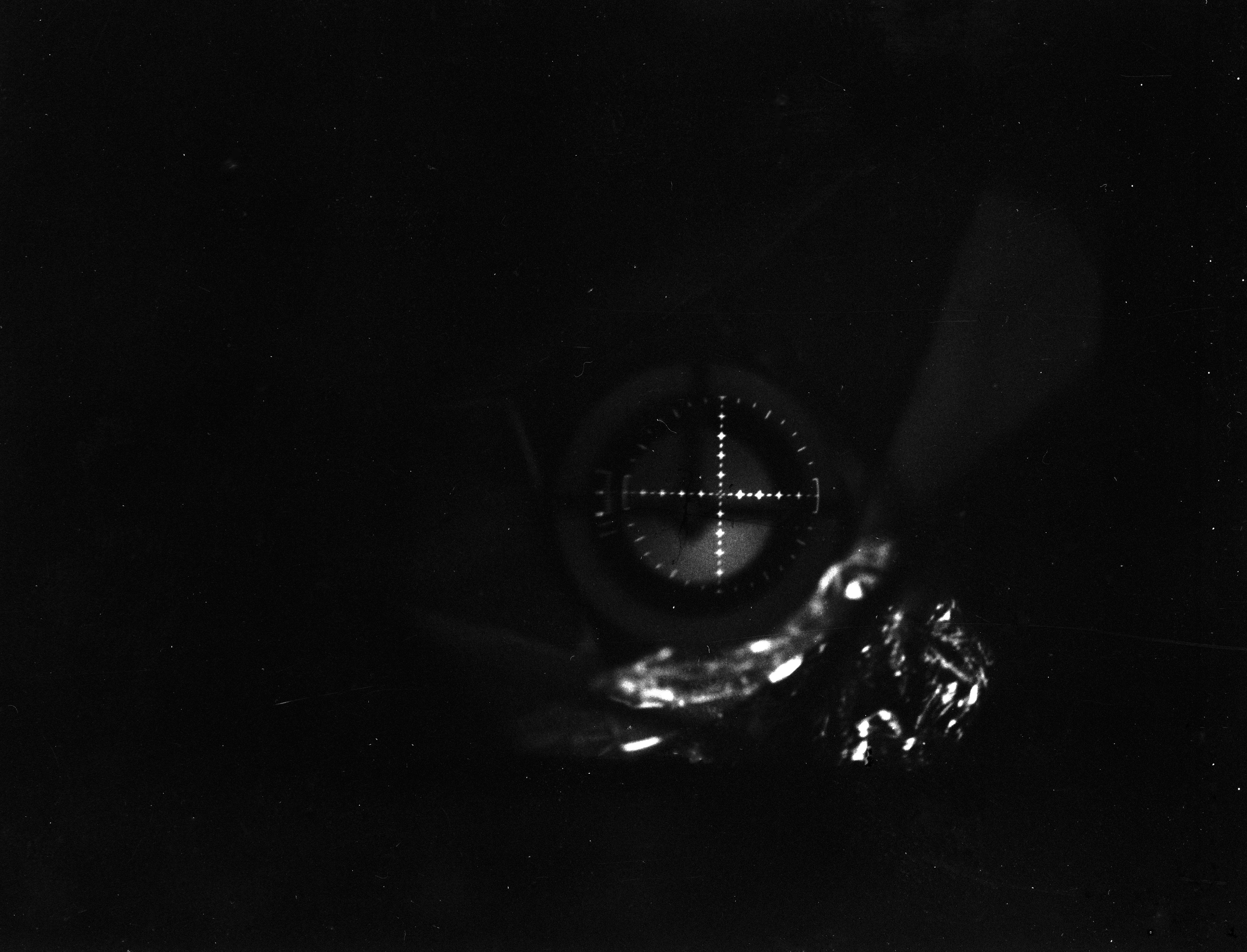
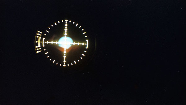
NASA Caption: Simulated views of the docking process
as seen by the Astronaut through the COAS (Crew Optical Alignment Sight).
NASA photo S69-28914.
Scan courtesy Jody Russell and Mike Gentry, NASA Johnson.
(Click on the image for a larger version.)
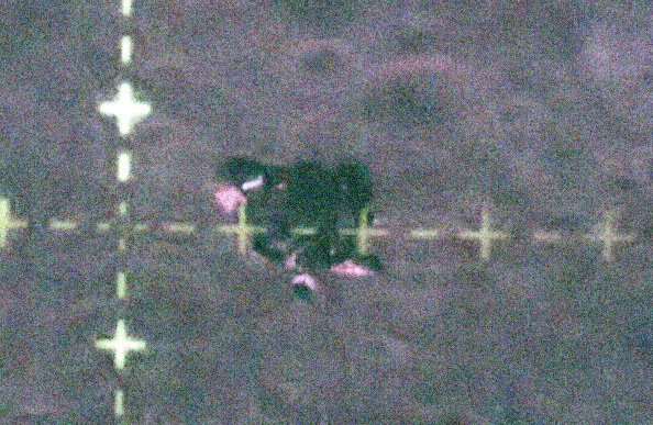
Apollo 14 Rendezvous Photo through the CSM COAS
KIpp Teague created this enhanced detail of AS14-74-10211, which shows the LM through the CSM COAS during rendezvous. Kipp writes, "I used a digital-camera noise-removal feature in Paint Shop Pro 9 to remove much of the noise, then curves-corrected the heavily de-saturated (color) in what was left." Paul Fjeld thinks that 10211 was taken through the left-hand rendezvous window - which he believes is framing the picture - with the camera held up close to the COAS.